In the past few days, I have implemented a device that mimics the remote control door of a garage with a Raspberry Pi and share it with you.
1. Remote control module
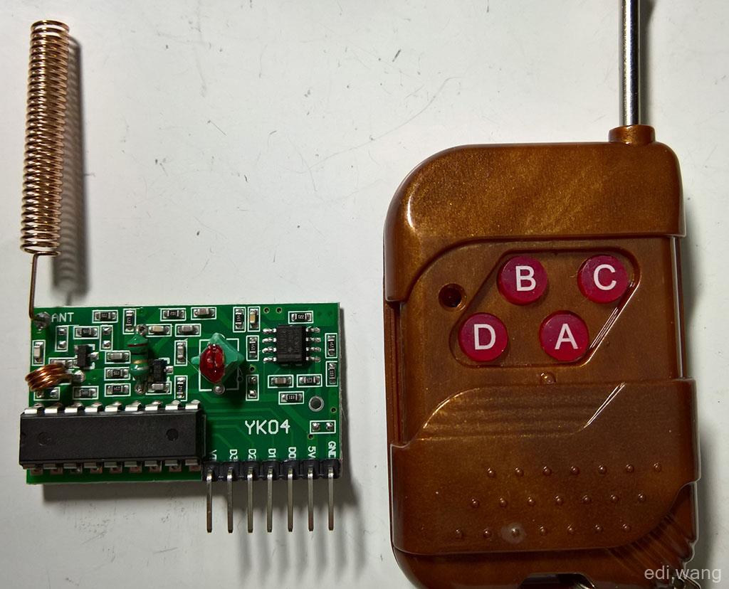
First of all, I will introduce the remote control and receiver board I use, this kind of remote control module can be bought everywhere in China, and it basically looks like this. Many roller shutter doors and garage doors use this remote control module. For radio experiments, the non-locking version is purchased, so note that it is best to purchase the antenna at the same time. The antenna is a 50 ohm single-core wire, in fact, it is a copper wire, pay attention to the frequency when buying, the radio license frequency in Chinese mainland is 315MHz, and 443MHz is also used abroad, and the remote control I bought is 315MHz. Note that the transmitting frequency and receiving frequency of the remote control should match. The remote control receiver chip is PT2272-M4, M4 means jog mode, that is, press and hold the remote control button to output a high level, release and stop the output. The ANT side of the remote control board is welded with the antenna in a vertical upward direction (relative to your device).
There are 7 interfaces on the remote control board:
|
PIN |
Description |
|
GND |
Ground |
|
5V |
5V power input |
|
D0 |
Correspondence remote control buttons |
|
D1 |
Correspondence remote control buttons |
|
D2 |
Correspondence remote control buttons |
|
D3 |
Correspondence remote control buttons |
|
VT |
Effective signal output |
Among them, D0-D3 corresponds to the four buttons A, B, C, D on the remote control. As for which is which, the module of each model is different, and you need to experiment by yourself. VT outputs high when there is a signal in D0-D3. That is, press any button on the remote control, and the VT will output.
It is important to note that the voltages of D0-D3, as well as VT outputs, are all 5V. However, the GPIO port of the Raspberry Pi receives a voltage of 3.3V, so it is necessary to divide the voltage to 3.3V with 2 resistors according to the voltage distribution law.
The law of voltage distribution refers to the fact that in a series circuit, the voltage distributed to each load is proportional to its impedance. The circuit implemented according to this principle is also called a voltage divider.
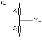
In a series circuit with only two impedances, the voltage distribution law formulas as follows:
![]()
So, I'm taking a 4.7K resistor and a 10K resistor, substituting the formula:
Vout = 5 x (10000 / (4700 + 10000))
It is equivalent to about 3.4v, which is acceptable for a Raspberry Pi.
2. Stepper motor
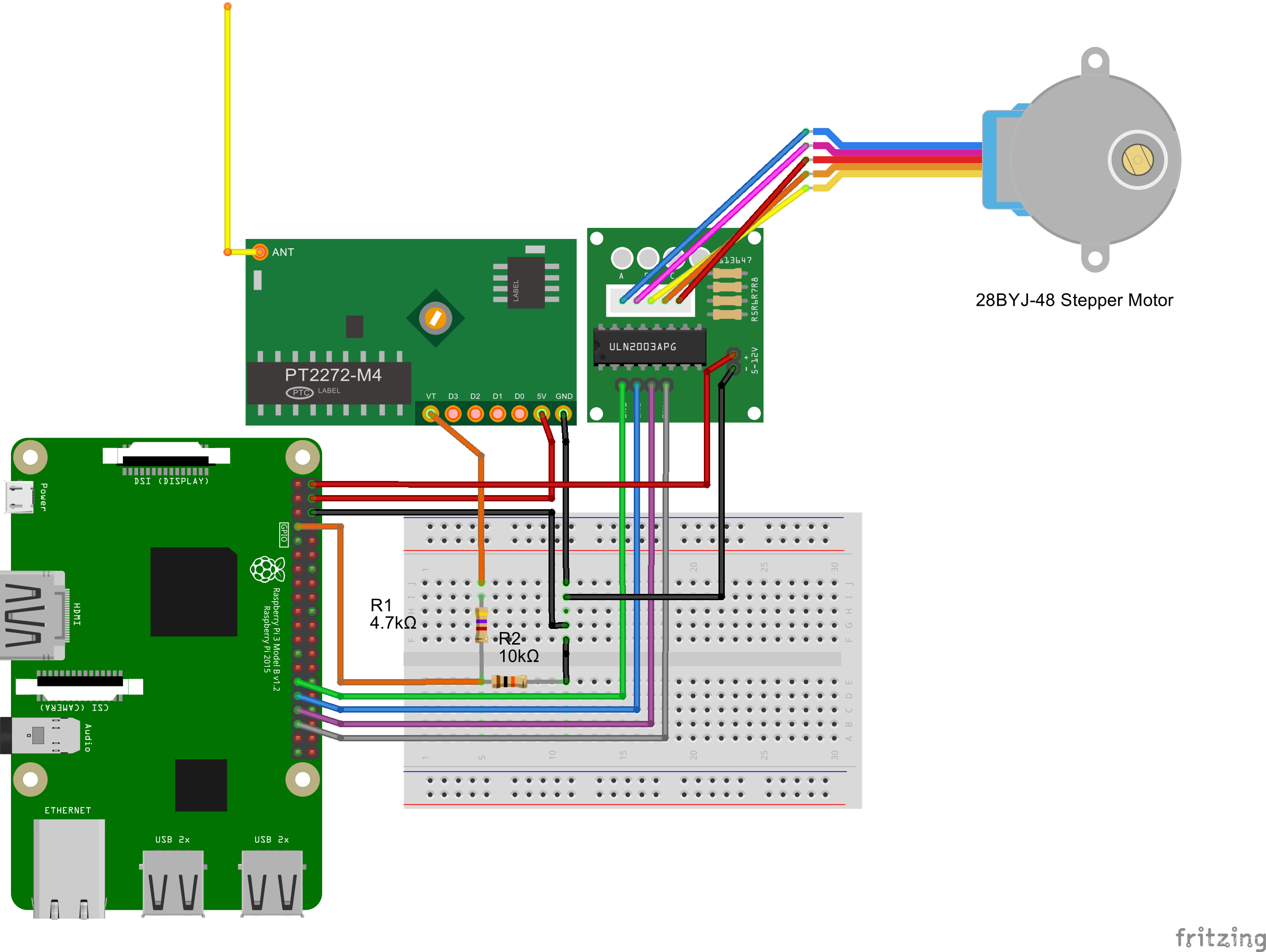
The stepper motor driver board I use is ULN2003, the stepper motor model is 28BYJ-48, and I have written an article on the blog before that ULN2003 drive the stepper motor, you can click here to read. So I won't talk about how to use it here.
3. Physical connection
In a nutshell, IN1-4 of the ULN2003 remote control board corresponds to GPIO ports 5, 6, 13, and 19. The VT of the remote control board corresponds to GPIO04. The 2 5V outputs on the Raspberry Pi power the remote control board and stepper motor, respectively. The connection is as follows:
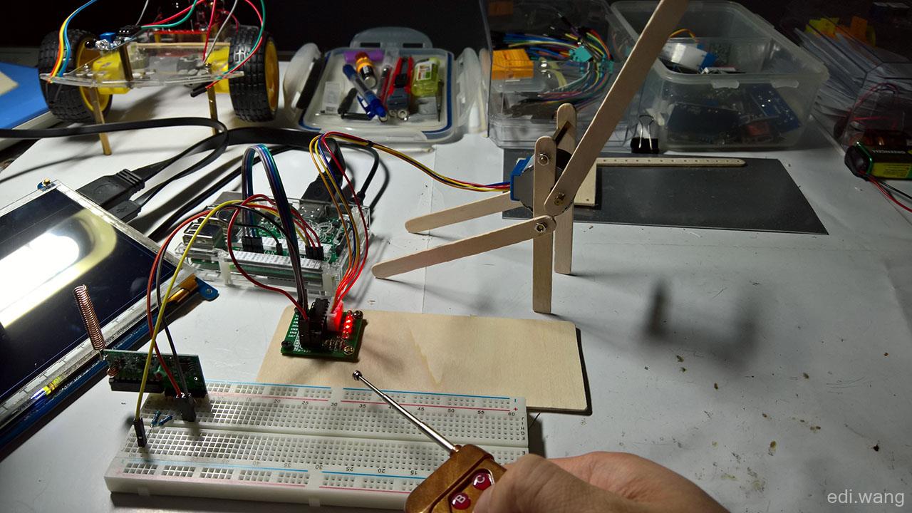
The stepper motor needs to make a bracket by itself, and I used an M3 caliber drill to make holes in the ice cream stick.
4. Write code
First, let's take one of the Uln2003 driver classes from this article and introduce it into the project.
Define an enumeration type to indicate the opening and closing state of the gate, and also define a bool type to indicate whether the motor is in operation or not.
public bool IsBusy { get; set; }

private DoorStatus Status { get; set; }

enum DoorStatus
{
    Open,
    Closed
}
Define GPIO controllers, ULN2003 stepper motor drivers, and GPIO ports on the VT side of the remote controller
public GpioController Controller { get; set; }

public GpioPin PinVT { get; set; }

public Uln2003Driver Uln2003Driver { get; set; }

public CancellationTokenSource Cts { get; private set; }
Define the method of opening and closing the door:
private async Task OpenDoorAsync()
{
    Cts = new CancellationTokenSource();

    await LogMessageAsync("Opening Door...");
    await Uln2003Driver.TurnAsync(90, TurnDirection.Left, Cts.Token);
    Status = DoorStatus.Open;
    await LogMessageAsync("Door is Open.");
}

private async Task CloseDoorAsync()
{
    Cts = new CancellationTokenSource();

    await LogMessageAsync("Closing Door...");
    await Uln2003Driver.TurnAsync(90, TurnDirection.Right, Cts.Token);
    Status = DoorStatus.Closed;
    await LogMessageAsync("Door is Closed.");
}
Main logic:
Controller = GpioController.GetDefault();
if (null != Controller)
{
    TxtMessage.Text += "[OK] GPIO Controller Initialized." + Environment.NewLine;

    Uln2003Driver = new Uln2003Driver(Controller, 5, 6, 13, 19);
    TxtMessage.Text += "[OK] Uln2003Driver Initialized on 5,6,13,19." + Environment.NewLine;

    Status = DoorStatus.Closed;

    PinVT = Controller.OpenPin(4);
    PinVT.SetDriveMode(GpioPinDriveMode.Input);
    TxtMessage.Text += "[OK] VT Initialized on GPIO 04." + Environment.NewLine;
    PinVT.ValueChanged += async (sender, args) =>
    {
        if (!IsBusy && PinVT.Read() == GpioPinValue.High && Status != DoorStatus.Open)
        {
            IsBusy = true;
            await LogMessageAsync("Remote Signal Received on VT.");
            await OpenDoorAsync();
            await Task.Delay(2000);
            await CloseDoorAsync();
            IsBusy = false;
        }
    };
}
5. Operation
Press any button on the remote control and the ice cream stick will rise. It automatically lowers after 2 seconds.
JZ
你好,请问你的树莓派是从哪里买的,可以给个店铺链接吗?想跟着你的博客学习一下